


-
Machinery
Choose from 19,871 used machinery listings
This information was originally published in Practical Engineering 1940 Vol1 No17. Information within this article is therefore correct as of 1940. The publication of this material aims to provide historical insight on the developments in engineering during this time period.
Users of pneumatic tools will be interested in a handy little pneumatic drill—the C.P. No. 3005 Power Vane drill—which has recently been placed on the market by the Consolidated Pneumatic Tool Co., Ltd., of 232, Dawes Road, London, S.W.6. This new tool weighs only 1Mb., so that it is particularly suitable for aircraft and other light metal construction jobs.
It is of sturdy construction and embodies all the features of the C.P. No. 300 drills but with more power. The standard equipment includes a 3/16in. chuck and push-button throttle. An optional extra is an offset handle, while angle machines can be fitted with either 90 deg., 45 deg. or 30 deg. heads, also extension spindles to suit customers' requirements. The overall length of the drill is 7 3/4in. and the speed, running light, is 2,500 r.p.m.
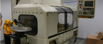
A new item just added to the range of workshop equipment marketed by E. H. Jones (Machine Tools), Ltd., Edgware Road, The Hyde, London, N.W.9, is the Phoenix Compacta. This device consists essentially of a tool cabinet designed on modern lines with the top table taking the form of a work bench, being equipped with swivelling motor, tool rest and vice.
The Compacta has been designed for use in either small or large factories, and for small shops constitutes a complete finishing bench. In large plants it can be used for all types of work in the correction of rejects and will also prove useful as an accessory installed in assembly departments where slight modifications are required in piece parts delivered from the manufacturing shops in order to secure good fits and to enable the reclamation of otherwise scrap work to be made.
The arrangement of the swiveling motor enables many different types of operations to be carried out efficiently. A finishing wheel is provided which can easily be removed from the taper spindle by means of a quick-release device, and the arrangement of the tool rest enables angular finishing work to be carried out efficiently.
For other types of work the motor can be swiveled up to 90 deg. to the right. Among types of work which can be handled successfully are : burring; scratch brushing and polishing; drill' grinding; file finishing; french polishing; and finishing.
The cabinet is provided with ample storage accommodation in the form of removable drawers and trays. It is also provided with a Yale-type lock. The motor is wired complete with lead ready for plugging into the electric supply and a switch is provided behind the top panel. It will be noted that the equipment is manufactured from sheet steel through-out and has been specially designed to avoid crevices so that it can easily be kept clean.
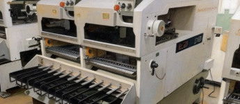
In a recent issue of Practical Engineering the electromagnetic system of crack detection was dealt with. A further interesting machine which operates on these principles is the E. and E. Magnaflux crack detector which is produced by the Equipment and Engineering Co., Ltd., of 2 and 3, Norfolk Street, Strand, London, W.C.2. There are several other models available. The type T.B. crack detectors meet the varied and numerous requirements of the automobile, aero and general engineering industries. These models are supplied with screw adjustment for the pole pieces so that the distance of separation can be easily regulated, and pole extensions, which are reversible and provided with vee slots for testing round parts.
Another popular model is the type S.A.I, which is used in garages and industrial concerns for small parts only.
The type S.B.I detector is a further model which has been developed to meet the demand for the rapid testing of small mass-production parts, particularly of a flat nature, such as cutters. With this equipment, a number of flat parts can be tested side by side at one time.
In the case of all the machines mentioned, the method employed is based on the electromagnetic principle. Briefly, this necessitates highly magnetising the part under test with a correct amount of magnetism (i.e., lines of force per square centimetre of sectional area). This is done by means of a powerful electro-magnet of special design, the two pole pieces of which are so shaped that the test-piece laid across them completes a closed magnetic circuit of low reluctance. If a crack exists, the lines of force will be broken, and will emerge on the surface of the part under test, forming opposite poles. The application of a suitable means of detecting the presence of the magnetic field will then display the crack. This is most conveniently done by pouring Magnaflux detecting-ink over the part. Granules incorporated in the ink adhere to the edges of the crack, showing up as a distinct line on the surface of the part. The result will remain visible, even when removed from the crack detector, until the ink is wiped off.
Do you have used machinery for sale?
Over 8,000 sellers have listed their surplus equipment with us since 2006.
Selling with Kitmondo is free, efficient and fast.
Start selling now