


-
Machinery
Choose from 20,248 used machinery listings
This article first appeared in Practical Engineering 1940 Vol1 No22. The information contained herein is accurate as of 1940. This article provides the enthusiast with notes on techniques employed in Engineering and Workshops at the time.
The necessity for balancing all rotating and reciprocating parts of machines is clearly recognised. Out-of-balance forces will sooner or later ruin bearings, cause foundation troubles, and if transmitted to driven machinery will result in endless troubles. This is particularly the case where electric motors are mounted on machine tools.
It is infinitely better to eliminate the need for balancing by machining components to a symmetrical shape. For instance, castings bored to receive a shaft invariably cause trouble unless the outside surface is trued to the bore. But where this is not possible it becomes imperative to balance all parts, as even the presence of a keyway in an otherwise symmetrical shaft will cause noticeable vibration at high speeds.
In general an out-of-balance force rotating in one plane may be counterbalanced by an equal and opposite weight in that same plane. But an out-of-balance force in two or more planes must be neutralised by weights rotating in two planes.
From this it is seen that the unbalanced force in a single plane varies directly as the product of the radius at which it acts and the square of the speed of rotation. At high speeds even a small weight can produce a very pronounced force.
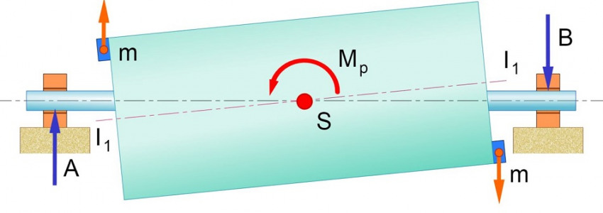
Let us now consider the problem of two or more planes. Even though the centrifugal force in each plane may be balanced by an equal but opposite force, there still remains a couple, which is the product of one force and the perpendicular distance between the planes. This couple tends to rock the shaft, setting up pronounced vibration. Hence, for complete equilibrium not only must the centrifugal forces be balanced, but also the vector sum of the resultant couples must be equal to zero. The centrifugal forces are now balanced, but there is left the couple of magnitude, the effect of which is to rock the shaft.
Turning now to reciprocating parts, we find that an out-of-balance force can only be completely neutralised by an equal and opposite reciprocating force. The problem of balancing forces set up in steam engines by accelerating and decelerating during each stroke is very difficult to deal with. The usual method is to produce partial balance by a rotating weight fixed on the crank extension opposite the connecting rod. In other words, the out-of-balance force is assumed to be concentrated at the crank-pin. This has the effect of counteracting the horizontal force, but it introduces a vertical component which acts alternately up and down. Usually only about 60 per cent, of this horizontal force is counterbalanced, as otherwise the vertical component might prove as disastrous as the effects of the original unbalanced force.
There are two methods of balancing rotating parts—static and dynamic. The disadvantage of the static method is that it does not take into consideration the effect of couples, and where the out-of-balance force is in two planes there is no method of telling in which planes to fit the weights.
A perfect balance can be obtained statically, but it should only be used for bodies of very thin section where couples are negligible. In the case of the rotor, even if the weight is split and half put in each plane, there still remains the couple. However, a static balance is infinitely better than no balance at all, and (this method is largely used for relatively narrow parts such as flywheels and couplings. It is also employed successfully for the balancing of parts such as rotors and armatures for very small fractional horsepower motors.
The component to be balanced is placed on parallel knife edges, where necessary being mounted on a mandrel, which should be checked for truth. The heavy portion will run to the bottom. Weight is then added to the fight side, or removed from the heavy side, until it will remain in any position. It is then in static balance. The knife edge blades must, of course, be perfectly true and horizontal, and the shaft must also be true. It is also advisable to have the centre of gravity of the body midway between the blades, to ensure equal distortion.
This is done in special machines in which the rotor or other part being balanced is mounted on two arms which are free to vibrate, either horizontally or vertically. It is run up to speed, when the out-of-balance forces set the arms vibrating. Then, usually by means of an eccentric cam rotating at the same speed as the rotor, forced vibrations are set up in springs.
These vibrations are adjustable, both as regards magnitude and position in each revolution. Suitable adjustment of both will completely neutralise the vibrations in each arm. In other words, the out of balance in the rotor can be found both as to position and magnitude. The springs are usually calibrated in inch-ounce units, so that the out-of-balance force can be read straight off. By adjusting for radius, weight may be added or material removed to effect the balance.
The usual method of working is to balance the job with plasticine. It is then removed from the machine and metal weights are fitted in place of the plasticine. The balance is then checked any small error in the weights being corrected. On no account should any hammering or drilling be permitted while the job is in the machine, as there will be a tendency for the shaft to spring, and the rocker arms and bearings may be damaged.
It is necessary to ensure that the shaft is perfectly horizontal in the arms, and that no out-of-balance force in the machine itself is transmitted through the drive. The coupling should also be balanced. The speed at which the job is run is important, in that it must be high enough for forces to have a measurable effect. Most machines run at between 400-700 r.p.m. In counterbalancing parts having narrow sections it is inadvisable to remove material, not only on account of any possible weakening effect, but also because we approach the plane through the centre of gravity of the body.
When it is decided to fit weights, they must be fitted in such a way that they cannot move or work loose. In direct current armatures, for instance, it is quite common to find a groove machined in the commutator clamping ring to receive the balance weights.
In rotating parts which are built up— such as armatures—a great deal can be done by statically balancing each part before assembly. In this way the out of balance in the completed armature is reduced to a minimum, and the problem of where to fit a large weight eliminated.
Do you have used machinery for sale?
Over 8,000 sellers have listed their surplus equipment with us since 2006.
Selling with Kitmondo is free, efficient and fast.
Start selling now