Kitmondo
13 May 2014
This article first appeared in Practical Engineering 1940 Vol1 No4. The contents within the article are accurate as of 1940. The article reviews various pieces of new equipment employed in Industry at the time.
Background
The various types of electro-magnetic and non-electric magnetic chucks in use today have, of course, speeded up production methods considerably; whereas thirty years ago this type of chuck was chiefly confined to small surface grinders, on which water or cutting compounds were not required, surface grinding today has become an important aspect of production. Magnetic chucks are now fitted to grinding machines of over 50 tons in weight, with a wheel drive of 60 h.p. while segmental grinding wheels enable heavier cuts to be taken.
The intermittent cutting action sets up considerable vibratory stresses in the face of the chuck, while cutting compounds, in volumes up to 40 or 50 gallons per minute, are freely used; it will, therefore, be realised that the modern magnetic chuck is necessarily a highly specialised piece of work. In addition to grinding, of course, magnetic chucks are also used in modern factories in conjunction with the lathe, planer and milling machine, chiefly when light finishing cuts are being taken in the latter cases.
Construction Details
For the benefit of those not familiar with modern designs of electro-magnetic chuck, the construction of the rectangular type might first be considered. The magnet and chuck body of the well-known "Humphreys" chucks, for instance, are cast from high-permeability magnetic steel in one piece. Around the core pieces so formed, the magnet windings are arranged so that the maximum area of core with the minimum stray magnetism is obtained.
The faceplate of the chuck is also machined from one piece, the poles being formed by cutting slots in the plate. The small bridges of steel between the individual poles are saturated with magnetism, the steel magnets in the body of the chuck being proportioned to ensure this without affecting the holding power of the chuck.
Consequently, this construction is free from the place by white metal or some other non-magnetic material.
The actual arrangement of the poles varies, of course, according to the duties which the magnet is intended to perform. Normally, the poles are of rectangular shape, spaced equally along the face of the chuck; this type is adaptable to most normal production jobs, being capable of holding castings and forgings in the rough, and dealing with work pieces affording poor contact surfaces.
In normal production schedules, however, castings which require vertical support between parallel steel blocks, or thin and narrow strips, or, again, parts which offer only a small area of contact to the chuck face, must often be dealt with. The most satisfactory type of chuck in this case is one having long, narrow, closely spaced poles. Very thin sheet can then be held without the necessity for an adapter plate, while special chuck blocks are not required. Flat pieces, gripped between ordinary solid steel blocks, can be held at any angle, while angle-iron or steel can be supported by a steel bar of suitable height. Circular bars can also be secured between steel blocks, while a piece having a mitred edge can be supported by a single suitably shaped bar of mild steel. Even prismatic pieces can be rigidly held between two suitably shaped bars.
Similar results can, of course, be obtained with the normal type of chuck, with conventionally spaced pole pieces, by the use of laminated chuck blocks.
With normal pole spacing no magnetic flux is available on the upper surface of a solid steel block on which the work is placed, but if a laminated block, made from high permeability steel plates separated by non-magnetic metal such as brass, is placed with the edges of the plates in the same axis as the poles of the magnet, magnetic flux will travel from the chuck to the work through some of the plates, and will return through others.
Accurate Location of the Work
Laminated chuck blocks are normally supplied in identical pairs, finished to very fine limits so that absolute accuracy in location of the work is automatically obtained. Pairs of blocks should not, of course, be mixed, and for this reason they are generally numbered and packed in protective boxes. A chuck block can, of course, have a triangular or half-round slot milled in it to accommodate workpieces of any special shape.
Somewhat the same principle of providing a larger number of poles is adopted in the case of adapter plates, which can be used on a conventional chuck for holding a number of thin parts. A further sketch indicates that with standard pole spacing, the amount of magnetic flux passing through a thin part is considerably reduced, whereas if an adapter plate consisting of a large number of closely spaced poles is adopted the greater number of paths provided for the magnetic flux enables a greater percentage of a total flux to be used.
A further advantage is that when dealing with a large number of small parts the whole of the energised area can be closely packed, whereas with conventional pole spacing the parts can only be arranged in rows across one edge of each pole, the remainder of the space being occupied by spacing strips.
The normal rectangular chuck is sometimes provided with a swivelling mounting, in order to facilitate grinding or machining angular or tapered pieces. A graduated ring is provided so. that accurate angles up to 90° on each side of the horizontal can be read off immediately. The advantage of this type of chuck for bevelling, flat-siding or edging the work should not need stressing, while taper grinding can also be carried out easily.
The Magnetic Sine Table
From this type of chuck to the magnetic sine table is a logical step. The magnetic sine table in effect is a magnetic chuck pivoted at one end to a plate which is in turn pivoted, at right-angles to the first pivot, to the base of the chuck. Thus, the advantages of a magnetic chuck and sine bar table are combined. Any single or compound angle is obtainable by placing standard gauge blocks under the rollers. Among the applications of a device of this type are the grinding of a compound angle on the face of a block, a typical instance of the accuracy being grinding a combination of angles of 5° 10' 32", and 10° 31'. Similarly, grinding a keyway in a tapered plug gauge, compound angle V-blocks, dovetails, slots, and so on, can be carried out with equal facility.
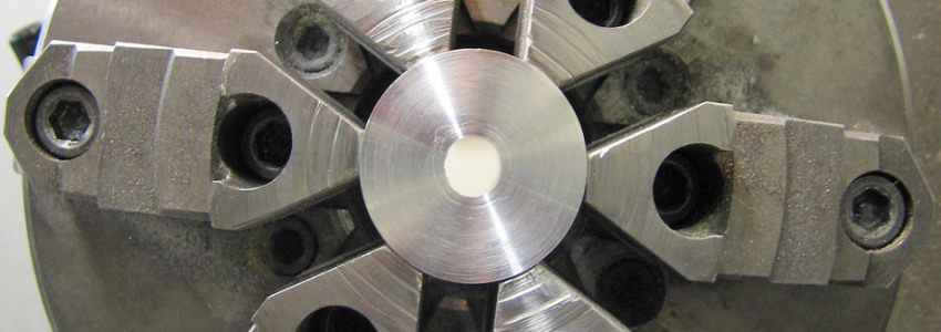
So far nothing has been said concerning the circular type of magnetic chuck. This type is, of course, of considerable value when fitted to a lathe, especially in the case of a hollow spindle machine. The electrical leads are then led through the spindle to small collector-rings sufficiently removed from the coolant and swarf to eliminate the risk of any electrical troubles. The current is supplied and returned through a brush holder having two spring-loaded brushes, carried on an arm which is bolted to any convenient part of the machine.
When an electro-magnetic chuck must be fitted to a solid spindle, however, the current is supplied through two slip-rings attached to the back of the chuck, a brush box being secured to a pillar at the required height. This is, of course, the only possible arrangement under the circumstances, but it suffers from the disadvantage that it is difficult to keep water or coolant away rings.
Non-Electric Magnetic Chucks
In this respect the non-electric Eclipse chuck has definite advantages, since no electrical connections are required and a chuck of this type can be quickly assembled to a lathe and used for a variety of purposes. By using the chuck as a magnetic faceplate, presenting a truly flat surface at right angles to the lathe spindle, turning thin discs or rings can be carried out with ease and rapidity, while an improvised tool-post grinder can be arranged so that surface grinding, internal grinding, or cylindrical grinding can be carried out.
Permanent Magnets
The principle on which the non-electric magnetic chuck operates may not perhaps be familiar to all readers. The body of the chuck contains nickel-aluminium magnets. The inner poles on the face of the chuck are of similar polarity, separated from the surface of the plate, which forms the outer pole of opposite polarity. The permanent magnet unit within the body of the chuck can be moved by a lever so that the magnets can be displaced relatively to the poles on the work-holding surface, thus de-energising the surface when required. The circular type of chuck is of similar construction, the movement of the internal magnets in this case being controlled by a key inserted through an opening in the rim of the chuck.
If the flux control is turned so that the working surface is partly energised, the work will be prevented from falling off the chuck face, but can be tapped into position, so that it can be centred accurately, using a dial gauge, for instance, as when boring holes to dead centre in the lathe with the aid of tool-makers' buttons.
Small rectangular, non-electric magnetic chucks, being readily portable, have advantages of their own. A chuck can be held in the hand while any parts adhering to it are brought into contact with a grinding, buffing or polishing wheel, or the small chuck can be gripped in the jaws of a vice while filing, scraping, or slitting small thin parts. Alternatively, the small chuck can be placed on the bed of a larger magnetic chuck, enabling two magnetic faces to be obtained at right angles to one another if required. Yet another application is the use of the chuck to hold parts vertically while marking out.
De-Magnetising
When parts are removed from a non-electric magnetic chuck they contain very little residual magnetism. In the case of electro-magnetic chucks the parts are de-magnetised by the use of a change-over switch which enables the magnetism to be momentarily reversed. Apart from the necessity for removing any residual magnetism in the parts which have been held, by a magnetic chuck, de-magnetisation of machine tools, such as drills, reamers, broaches and milling cutters, will also be necessary from time to time if they have been in use on a machine fitted with a magnetic chuck. A tool such as a milling cutter, for instance, will collect the cuttings if it becomes magnetised, leading to loss of time, and inferior workmanship.
Two types of de-magnetiser are in general use: the platen type, in which, the parts are laid on the flat surface of the de-magnetiser, and the aperture type, through which the parts are passed. The platen type is of most general application; it is usually sufficient simply to pass the parts over the platens, which are influenced by laminated magnets in the base. The magnet coils are energised by an alternating current, thus producing a rapidly-changing polarity on the faces of the platens. It will be appreciated that this type of machine is considerably more effective than the old method of employing a rotating magnet between two masses of laminated iron plates. If alternating current supply is not available, however, a rotary transformer must be employed to convert direct current to alternating, or a generator producing alternating current must be driven by a belt.
Aperture de-magnetisers are capable of handling a quantity of small parts very rapidly, since small components can be slid through the aperture on an inclined chute: long parts such as bars can be passed through by hand. An advantage of this type is that items which-could not be dealt with satisfactorily on a platen type de-magnetiser can be completely de-magnetised without dismantling, since no contact between the magnets and the parts is necessary. Aperture demagnetisers have a much higher current loading than the platen type. They should, consequently, be switched off whenever possible in order to prevent overheating, and are better suited to intermittent operation.

