


-
Machinery
Choose from 20,089 used machinery listings
This article first appeared in Practical Engineering 1940 Vol1 No4. The information herein is accurate as of 1940. The article describes developments in Manufacturing at the time.
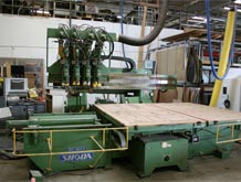
In the machine shop the rough castings or forgings from the foundry pass through a number of successive operations, eventually emerging as finished parts ready, after inspection and test, for the assembly line. The batteries of machines are so arranged that the sequence of machining operations on any given component follows a logical order. In many cases each machine is driven by its own electric motor, eliminating the overhead shafting and belting which is so often a source of accidents, while the parts are carried from one machine to another on overhead or bench-level conveyors.
One of the most important items in the modern machine shop is the universal milling machine. Originally designed for the purpose of forming the spiral flutes in twist drills, it is now adapted to a wide variety of machining operations. Basically, the milling machine consists of a rotating spindle or arbor on which a cutter provided with a number of hardened cutting edges or teeth is carried. The arbor may be horizontal or vertical, while below the cutter is an adjustable table to hold the work, so that the parts being machined can be fed up against the cutter, moved crosswise or lengthwise in relation to it, or rotated at the same time. When a number of machining operations have to be performed on one part, a rotating table located by a series of stops and known as an index head is rotated through one-sixth of a revolution, and a fresh cut taken, further revolutions of the index head being made until all the faces of the hexagon have been milled. This process is known as rapid indexing, and is capable of elaboration to provide almost any sequence of machining operations.
Different forms of cutter are used to produce various surfaces and profiles on the casting or forging. The plain milling cutter cuts a flat surface parallel to its axis, the wider cutters usually having helical teeth in order to prevent chatter. Narrow plain cutters are used for producing grooves, splines, keyways, etc. Side cutters, as their name suggests, have the cutting teeth on their side faces. Two are often arranged on an arbor a short distance apart in order to mill both sides of the component simultaneously, an example being a valve rocker, which is clamped to the work-table and passed slowly between the rapidly rotating cutters.
A face mill has the cutting teeth arranged on its outer face, and is used for machining flat surfaces, such as cylinder heads, etc. An end mill cuts both along its length and at the end, and is used for machining squared shoulders, and for cutting slots and some keyways.
As a practical example of the use of milling machines, operations on a motorcar cylinder block casting after it has been cleaned up on leaving the foundry by shot blasting and "pickling" for an hour and a half in a weak solution of sulphuric and hydrochloric acid, followed by immersion in a hot soda solution to neutralise any remaining acid, usually commence with the milling of the cylinder head and sump joint faces, the cutters usually being of the face type, with inserted blades. Often the milling machine has a rotating work-table with two vertical spindle cutters, one of which takes a rough cut, and the other a finishing cut, the table being rotated to bring the casting under each cutter in turn.
When the cylinder head joint face and the sump face have been accurately machined, the casting can be positioned for the various other machining operations, such as milling the timing cover flanges, manifold joints and similar points. The main bearing housings also call for accurate machining, end-mills and side cutters generally being used to face up the various surfaces.
Apart from the milling machine, the shaper is sometimes used, chiefly to produce flat surfaces. Although there are many different designs, the principle of the shaper is illustrated in an accompanying sketch. It will be seen that the surface of the metal or casting is "planed" by the tool carried at one end of a ram. The ram forces the tools lowly forward across the metal, with a quick return at the end of the stroke. During the return stroke the table carrying the vice in which the work is clamped is moved sideways slightly so that the next cutting stroke takes place on a fresh section of the casting. The ram itself is moved by a rack-and-pinion gearing, or by a crank driven from an eccentric. The planer or shaper, however, has not the wide scope of a milling machine.
A broaching tool has a number of applications in a modern factory. At one time, for instance, the splines in gear wheels were cut separately; now, however, they are produced simultaneously by means of a broach, which takes the form of a long, tapered bay, provided with sharp cutting edges in parallel rows. The narrow end of the broach is passed through the plain hole at the centre of the gear wheel, and the coupling of a hydraulic or mechanically operated ram attached to it. This pulls the broach through the gear, the cutting edges producing the splines. The final length of the bar is parallel, and is often provided with finer teeth, so that a good finish is obtained.
Apart from forming splines, broaches are used to produce plain bores in gear wheels and bearings, and for machining such parts as connecting rods. In the case of split big-end bearings, each half may be separately broached by a D-shaped tool. Sometimes the broach is passed through the bearing before it is split to form the two halves. Broaches with flat or specially shaped cutting surfaces are also used in some cases for external finishing of connecting rods and other components. In this case the cutting teeth are arranged vertically behind the work-table, and the work is fed up against them.
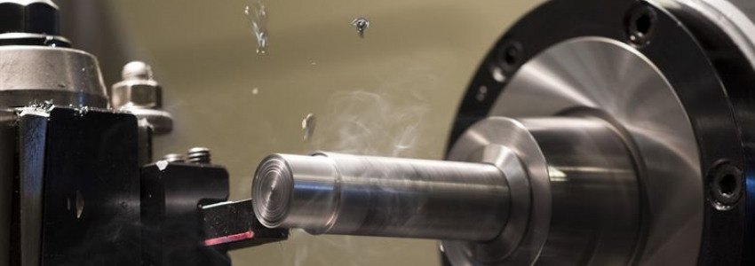
The rough castings or forgings of a large number of parts, such as pistons, crankshafts, etc., and similar circular components, are usually brought to the finished shape by turning in a lathe. This is similar in essentials to the ordinary workshop lathe, the chief difference being the very wide range of attachments provided, while control is largely automatic. It is usual for a number of operations to be carried out simultaneously. The rough turning and finish-turning on a layshaft gear cluster, for instance, may be carried out on an automatic lathe on which as many as seven tools are carried by the front slide, in order to produce the correct diameter at various points along the shaft, while shoulders and radii are simultaneously produced by five tools on the rear slide.
During the finishing operation an additional slide may be added, operating from below, and carrying tools to chamfer the edges of the gear collars. When dealing with back axle casings, special designs of lathe enable both ends of the axle housing to be machined simultaneously. Twenty or more tools may be in use at once.
A diamond-tipped tool is frequently used in the lathe when an exceptionally accurate finish is required. When turning out the white metalled bore of a big-end bearing, for instance, it has been found that a diamond produces a particularly smooth and long-wearing surface. Similarly, on soft metals, such as aluminium, only diamond boring is usually considered to give the degree of accuracy required in modern engines in the case of machining operations on pistons, diamond turning being used when finishing the gudgeon pin bores and finish-turning the outside diameter.
Crankshafts are usually turned in lathes of very heavy structure designed solely for this work. The various journals and flanges are machined in turn, elaborate precautions being taken to ensure that the shaft is correctly centred, and that whip or distortion is avoided. Similarly, the rough camshaft forgings are turned on special lathes on which the cutters for each cam are controlled by master cams, to form the correct cam profiles on the shaft.
After machining or turning operations, oilways and stud holes have to be drilled in a number of components. Multiple drilling machines are used in most cases, as many holes as possible being drilled at one operation. At the Ford works, for instance, a machine controlled by one man drills 92 holes in the "V-8" cylinder block casting in 35 seconds. On Austin engines a multi-spindle tool simultaneously drills 53 holes in both ends, one side and the top of the engine casting, the drills advancing from four sides, and withdrawing automatically when the end of their feed is reached. Very similar is the threading operation, in which the taps, after having cut the thread in each hole, reverse their motion and screw themselves out.
A tricky job is the drilling of crankshaft oilways. The crankshaft is mounted in a fixture either horizontally or vertically and long, slender drills, each driven by an independent overhead electric motor, are fed into the webs by rotating a hand wheel. The operator skilfully feeds the drill forward and then withdraws it, repeating the action until the passages are complete.
Whenever machined parts have been case-hardened, final finishing must be carried out by grinding with an abrasive wheel, or by lapping with abrasive compounds, as normal machine tools make no impression on the case-hardened surface. The part is machined to very nearly its final size before hardening, but some allowance must be made for the slight distortion which usually takes place during carburising, reheating and quenching. Where a flat surface is concerned, the final finishing is carried out by passing the component under a rapidly rotating grinding wheel. The wheel is automatically trued up by a diamond-tipped tool before each cut is taken.
This procedure is often followed in the case of the top and bottom faces of a detachable cylinder block, and the top faces of normal cylinder blocks and crankcase castings; although these are not case-hardened, the grinding enables a very accurate surface to be obtained, essential in this case to prevent gasket leakage. In many cases the cylinder blocks travel under the grinding wheel while held on the magnetic bed of the surface grinder.
When splines have to be ground on a shaft after hardening, the shaft is mounted between the centres of a spline-grinding machine, and the grinding wheel passed along each spline, the shaft being rotated to bring another spline upwards when one is finished. Where gear teeth are concerned, the grinding wheel is specially. shaped in order to provide the correct tooth form.
Internal bores of gear wheels and similar components which must be accurately finished, perhaps to take a ball race, are ground with the aid of a small grinding wheel running at high speed on the end of a spindle which can be passed into the bore. At the Morris works the gear bores are finish-ground in this manner, the grinding wheel spindle rotating at over 12,000 r.p.m., while the gear itself is being rotated at 450 r.p.m.
The flanges and journals of crankshafts are usually finish-ground by mounting the crankshaft in a special machine so that the journal is rotated at high speed while the grinding wheel is passed along it. Camshafts are ground after hardening, in yet another special grinding machine, in which the cut is controlled with extreme accuracy by moving the shaft towards and away from the grinding wheel, so that the correct cam profile is obtained.
Short circular parts are ground in a centreless grinding machine. Instead of mounting the part between centres, it is passed across the face of the grinding wheel, and at the same time guided by a rotating control wheel ; the part meanwhile rests on a fixed support, as shown in an accompanying sketch. By suitably positioning the grinding wheel, support and control wheel in relation . to one another, a part can be accurately finished to within .0001in. Parts such as gudgeon pins can be fed from a hopper, passed automatically across the face of the grinding wheel, and accurately finished at the rate of 100 or more pins an hour.
By altering the shape of the grinding and control wheels, moreover, tapered work or several different diameters on one shaft can be produced with great accuracy.
It will be appreciated that throughout the machine shop each cutting tool must be fed with a supply of special coolant; this is a liquid which combines lubricating with cooling properties, and is fed on to the work from pipes adjacent to the points at which cutting is taking place. Although most of the coolant is caught and returned for reconditioning, some of it remains in the metal turnings and cuttings. Before these are loaded into trucks or compressed into small bricks in order to be returned with other scrap metal to the furnaces, the cutting oil is reclaimed by centrifugal separators. No less than 14 gallons of oil is reclaimed from 1-1/2 cwt. of "swarf." Four thousand gallons of oil are reclaimed weekly.
Do you have used machinery for sale?
Over 8,000 sellers have listed their surplus equipment with us since 2006.
Selling with Kitmondo is free, efficient and fast.
Start selling now