


-
Machinery
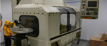
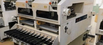
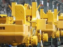
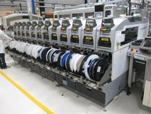
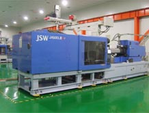
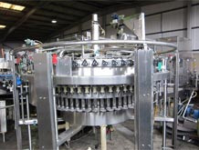
Choose from 20,279 used machinery listings

This article first appeared in Practical Engineering 1940 Vol1 No5. The information within the article is accurate as of 1940. This article reviews Tools used in Engineering at the time.
If a machine tool is to fulfil the requirements of modern production methods, involving the use of high-speed cutting alloys, it must be of extremely rigid design, built to the finest limits of accuracy and capable of running for prolonged periods with the minimum of attention. At the same time, it must be easy to operate.
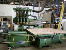
The Soag-Standard shaper, which is the subject of this week's machine tool review, is claimed by the makers (Soag Machine Tools, Ltd., 7, Juxon Street, Lambeth, London, S.E.ll) to possess all these desirable attributes, together with many other outstanding features.
To meet the demand for accuracy, the column and base plate are cast in one piece and heavily ribbed to withstand the heaviest stresses when taking deep roughing cuts. Strong radial and axial ribs on the interior side of the column stiffen the machine and eliminate deflections. The guideways of the ram are also strongly ribbed,, the surfaces being chilled during casting. These guideways are rectangular in shape, as it has been found that this design takes up bending stresses better. Play is eliminated by taper gibs running over the full length of the column, and the guide ways are provided with felt wipers to retain the oil collected by the ram and to keep the surfaces clean.
The cross slide travels on the column in wide, rectangular guideways which are provided with adjustable gibs. The vertical adjustment of the cross slide is by a hand-operated leadscrew of ample dimensions. The upper guideway for the saddle on the cross slide is rectangular and the lower one is prismatic. All guideways are chilled to obtain a close and hard-bearing surface. The Brinell hardness is about 200.
The box-shaped table is specially designed to eliminate deflections when machining parts fixed to the side of the table. Along the top surface are three tee-slots, and on the left-hand side are two horizontal tee-slots, while on the right-hand side are two vertical tee-slots and one vee-slot for clamping cylindrical parts. When it is necessary to fix large work directly on the saddle, the table can be removed. Normally it is fixed to the saddle by strong bolts, and its position is ensured by a square key.
The table feed can be operated by hand or automatically in both directions. There are four different automatic feeds ranging from .01in. to .04in. per stroke. The vertical adjustment of the table is by hand through worm and spindle.
Eight speeds ranging from 14 to 148 strokes per minute are provided by the gearbox which is a completely enclosed unit mounted at the side of the column. The various speeds are selected by a single lever, but a separate lever.operates the back gearing. The gears themselves are made of chrome nickel steel and the tooth profiles are case-hardened and heat treated. The multiple spline shafts on which the sliding gears are mounted are milled from the solid. All gear-box shafts run in ball bearings, and an oil bath is provided to ensure efficient lubrication.
The specially made rocker arm is a casting of great tensile strength, and is connected to the ram by means of a link.
The latter draws the ram down on to the guideways during the cutting stroke so that it offsets any upward pressure of the cutting tool. With this design, the weight of the rocker arm is not hanging on the ram, but is taken up by a bearing at the lower end of the rocker arm—an arrangement which is claimed to diminish wear on the guide-ways and absorb less driving power. To ensure adequate support, even when using the maximum stroke, the ram is of exceptional length and runs in long guideways. Strong ribs give the ram great rigidity and help to eliminate vibration or deflections.
A finely graduated scale is provided on the toolhead to enable it to be set at any desired angle. The front part, with the clapper box for lifting the tool during the return stroke, is adjustable to enable the tool to be set to the most suitable angle for the work being done.
There is also an adjustable taper gib for the guideway of the toolhead. Normally, the vertical feed of the toolhead is by hand, and for this purpose the lead screw is provided with a graduated dial, but on request the machine can be supplied with an automatic downfeed to the toolhead.
So that the operator can observe the tool when adjusting its position, the handle for the adjustment of the ram is placed close to the toolhead. Both the length of the stroke and the position of the ram can be altered while the machine is in motion.
The shaper is normally supplied with a single flat belt pulley for driving from a Line shaft, but if desired it can be fitted with direct electric motor drive with vee-belt transmission. In this case, the machine is provided with a 4-groove vee-belt pulley and a motor bracket at the rear of the machine. In either case, a friction clutch, operated by a handle within easy reach of the operator, transmits the power from the driving pulley to the gear box. The use of high-grade materials and the most careful workmanship enable the makers to guarantee this machine to be accurate within the following limits:
Surfaces parallel within .0008in. per foot.
Surfaces at right angles square within .0012in. per foot.
Following the recent reports of a German self-sealing petrol tank which is virtually impervious to repeated hits by bullets or shell splinters, comes news of a British "bullet-proof" petrol tank which is now being extensively used in the R.A.F. At the Air Ministry's experimental station, a sample tank was tracers, at close range, but refused to leak or explode. Filled with 60 gallons of petrol, it was then dropped 60ft. or to a blazing patch of oil, but did not explode or catch fire.
The design of the tank is, of course, a closely guarded secret, and for that reason we are unable to publish details of the principles on which it is based or the methods employed in its construction.
Do you have used machinery for sale?
Over 8,000 sellers have listed their surplus equipment with us since 2006.
Selling with Kitmondo is free, efficient and fast.
Start selling now