English
 Français


-
Machinery
Choose from 20,020 used machinery listings
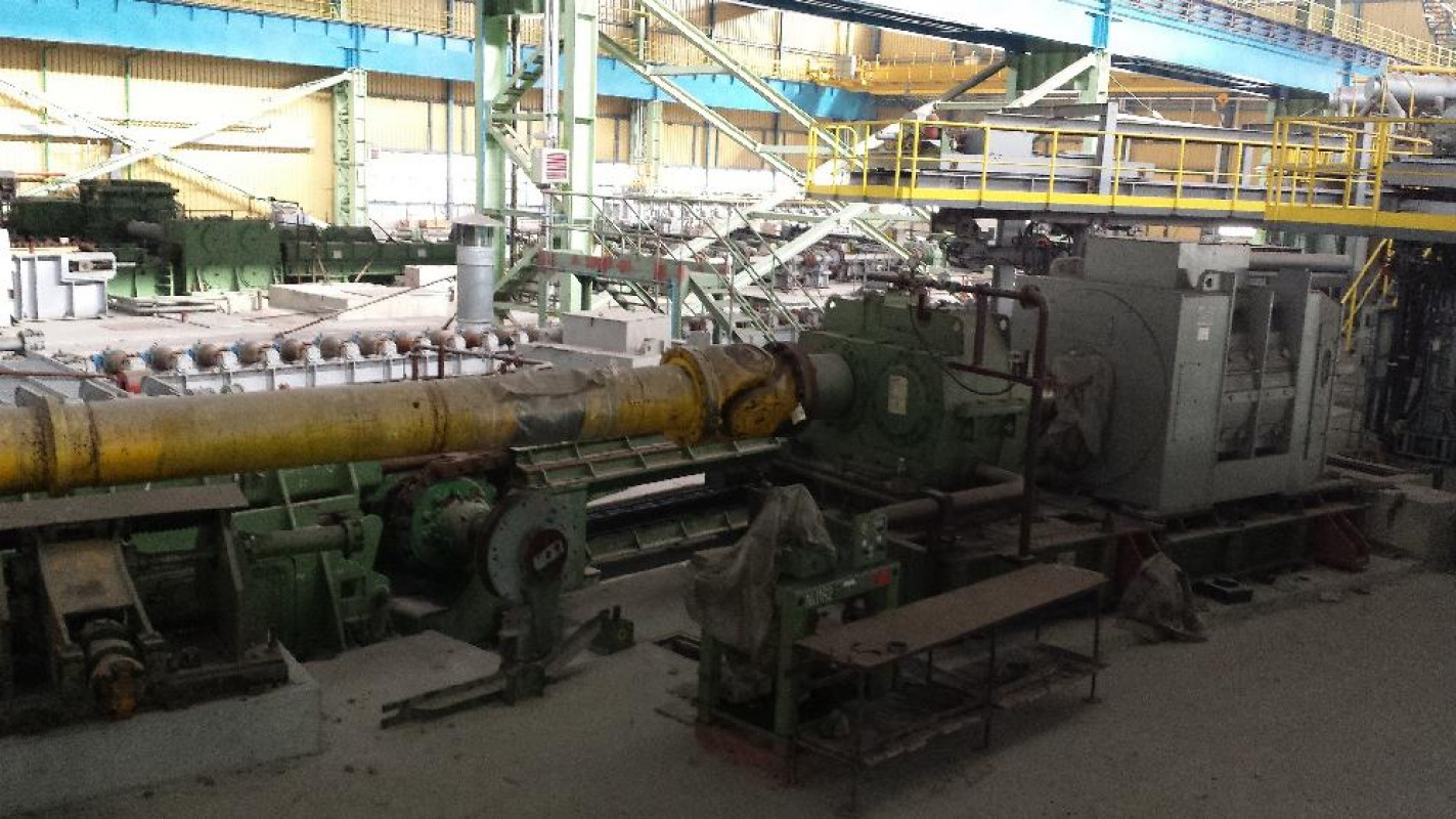
Description Seamless Tube Production Line
Year 1985-2004
Brand SMS-MEER
Qty. 1 Second-hand seamless pipe production line (investement value approx. EUR 200 Mill.)
Mfc. Mannesmann Meer Type
Continuous Pipe Rolling Mill for production of seamless, steel tubes
Entry billet dim. dia. 170 x 8500 mm length
Exit Pipe dim. dia. 21.3 - 159 mm
Wall thickness 2.3 - 25 mm
Length 6 - 16 m
Capacity (design) 150 000 T/annum can be xtended up to 400 000 T/annum
Line and constructional pipes with diameters 21.3 - 159.0 mm
Drill pipes casing and line, with diameters
Pipes for machine industry diameters 21.3 - 159.0 mm made of steel featuring fine-grained structure and steel for quenching and tempering
Boiler pipes with diameter 21.3 - 159.0 mm
Pipes made of ferritic alloy steels diameters 60.3 - 139.0 mm
of the following types
line and construction pipes installation pipes boiler tubes (grade I – III)
pipes for cold working pipes for further processing into drill pipes
Made of straight carbon, medium-alloy and low-alloy steel.
Hot-rolled, seamless, steel tubes according to the standards of
DIN, ASTM, API5, CT, API5L, BS, GOST, PN
Continuous Pipe Rolling Mill was scheduled for an annual production capacity of 150 000 tons. The pipe manufacturing process according to MRK-AR technology consists of rolling of thick-walled tubular blanks on a cylindrical mandrel which is moving at a controlled speed rate along the rolling axis. At the end of rolling process charging tube is removed from a mandrel. It’s a modern solution applied in tube rolling mills of high productivity and for much larger size ranges of rolled tubes. Due to the use of a continuous mandrel rolling mill the rolling process is limited to pipes with diameter of less than 244.5 mm. The technological line is composed of the following devices
Rotary heating furnace Walking beam furnace Rotary piercing mill
Mill reducer bushings
Continuous mandrel mill Mandrel hoist
Pipe induction reheating unit Stretch reducing rolling mill Walking beam cooling bed
End finishing line No.1 Dia.
Length 6 - 12 meters
End finishing line No.2 As above the line No.1!
End finishing line No.3
Dia. 44.5 – 159.0 mm
Wall thickness 4.5 – 25.0 mm,
Length 6 - 16 meters
Space of the existing line 14253 m² Complete area
Please advise if further information is requested.
LP Description Built QTY.
Rolling stands MRK-AR and HRW - Roll housings of the rolling stands 1980 20
Base body of continuous rolling mill 1980
2000 1
PUMP Type 30 D17 - 2x2G1 0/3, Prod.-No 86907, Prod. WAFAMP Warsaw 2000 2000 1
PUMP Type 30 D17 - 2x2G1 0/3, Prod.-No 86906, Prod. WAFAMP Warsaw 2000. 2000 1
PUMP Type 30 D17 - 2x2G1 0/3, Prod.-No 86908, Prod. WAFAMP Warsaw 2000. 2000 1
PUMP Type 25 D17 - 2G1 0/3, Prod.-No 86941, Prod. WAFAMP Warsaw 2000 2000 1
PUMP Type 25 D17- 2G1 Prod.-No 86939, Prod. WAFAMP Warsaw 2000. 2000 1
PUMP Type 25 D17 - 2G1 0/3, Prod.-No 86940, Prod. WAFAMP Warsaw 2000. 2000 1
PUMP Type 25D17 2x3G1 0/2 Prod.-No 86904, Prod. WAFAMP Warsaw 2000. 2000 1
PUMP Type 25D17 2x3G1 0/2 Prod.-No 86905, Prod. WAFAMP Warsaw 2000 2000 1
PUMP Type 25D17 2x3G1 0/2 Prod.-No 86903, Prod. WAFAMP Warsaw 2000 2000 1
Self-cleaning filter HYDAC Type RF-3-4 Prod.-No CF-4449/99, Prod.
HYDAC - Mikołów 1999. 2000 1
Self-cleaning filter HYDAC Type RF-3-4 Prod.-No CF-4450/99, Prod.
HYDAC - Mikołów 1999. 2000 1
Rubber expansion joint with flange, type ERV-CR 300 2000 3
Manual shut-off butterfly Valve DN 400 2000 2
Manual shut-off butterfly Valve DN 600 2000 1
gantry crane Q = 3.2 T Prod.-No 45987, Prod. GZUT - Gliwice 2000 2000 1
Transport flip-flop 1 2000 1
Transport flip-flop 2 2000 1
Transport flip-flop 3 2000 1
Motors - main drives of the continuous rolling mill KWW 1980
2000 1
Rolling stands of the rollers MRK-AR and HRW - rollers with chocks 1980
2000 18
Bogie hearth furnace for tempering the mandrels 2000 1
Steel chimney of the furnace 2000 1
Tube reducing mill (without stands and motors) with lokal operating statons 2000 1
Layer saw LS type FST 017 KKS 1430 2000 1
Motors 28 x 350 kW 2000 28
Rolling accessories - complete stands - 137 pcs (used) 137
Rolling accessories - complete stands - 74 pcs (new) 2000 74
Rolling accessories - cross-stands (without rollers) - 12 pcs 2000 12
Measuring quality assurance system - QSS 2000 1
System of the computer-aided rolling process CARTA 2000 1
Preheating furnace VWO 2000 1
Setting devices of AC and DC - 01A9E2+B1D2, 5 field cabinet 2000 5
Setting devices of AC and DC / Note for both furnaces/
- transport of the charge to the heating furnaces 01A9E1+B1D1, 7 field
cabinet 2000 7
Setting devices of AC and DC - 01A9E3+B1D3, 6 field cabinet 2000 6
Setting devices of AC and DC / transport of the charge to both heating
of the charge to both heating furnaces 01A9E1+B1D1, 7 field cabinet 2000 7
Individual station of power hydraulics for the preheating furnace 2000 1
Individual station of power hydraulics for the rotary furnace 2000 1
Device of plastic lubricant lubrication for rotary furnace 2000 1
Device of plastic lubricant lubrication for preheating furnace 2000 1
Equipment of the central hydraulic station - tank V-40 000 L with installations 1980
2000 1
Equipment of the central hydraulic station - pumping engines 19 pcs. 1980
2000 19
Equipment of the central hydraulic station - oil filters 6 pcs. 1980
2000 6
Equipment of the central hydraulic station - 3 stations of hydraulic accumulators 1980
2000 3
Rotary furnace DHO 1980
2000 1
Control and visualisation of the area of heating furnaces and hot shearing machine 2000 1
Control system of the rotary saw - control and visualisation (MMI-VPC) 2000 1
System of computer-aided temperature of the walking beam furnace and rotary furnace Giwep 2000 1
Switching devices of alternating current of the hot line - 6 switching devices R16 - R21 1980
2000 1
Technological equipment of the pumping station - pipings with fittings 2000 set
Reeling mill SWW 1980
2000 1
Accessories reeling mill SWW 1980
2000 1
Continuous rolling mill KWW, without motors and stands 1980
2000 1
Control and visualisation - page 270 item 1.2. 2000 1
Lubrication of mandrels DSS with control unit /common for JENI 94 and 100/ 2000 1
Bloom removing rolling mill AZW 2000 1
Rolling stands 21 pcs rolling mill - bloom removing mill AZW 1980
2000 1
Oil lubricating device - individual systems mandrel retainer 1980
2000 1
High pressure water station - pumps 1980 2
Saw for cold cutting of the charge, manufacturer Wagner type KH44H/DG Nr 42208 -1980 with chips and waste material removal, with hydraulic and electric station and installation - control box AH02E00+E100colli 275, 276, 277 1980 1
Feeding and receiving device of the saw, incomplete with power and control box /JENI 178/. 2000 1
Device for re-equipment of the stands of the continuous rolling mill and hollow reducing mill 2000 1
Device for lubricating with plastic lubricant - central systems I, II, III, IV-pumps 2000 1
Machine tools for calibrating the stands of the reducing mill Becker KR III 33 with control boxes 1996 3
Programmable logic controllers PLC or the reeling mill SWW 2000 1
Programmable logic controllers PLC or the reducing mill SRW 2000 1
Shearing machine for hot shearing WAS 2000 1
Electric equipment of the shearing machine for hot shearing 2000 1
Transport between rotary furnace and reeling mill 2000 1
Plastic lubricant lubricating device for mandrel retainer 2000 1
Distributing pipes of the technological network - pipelines of the plastic lubricant -
system I - reeling mill 2000 1
Distributing pipes of the technological network - pipelines of the plastic lubricant - system II - first line, continuous rolling mill 2000 1
Distributing pipes of the technological network - pipelines of the plastic lubricant
- system II-second line, transport devices before reduction mill 2000 1
Distributing pipes of the technological network - pipelines of the plastic
lubricant - system III - pipe cooling bed with feeding and exit rollways 2000 1
Distributing pipes of the technological network - pipelines of the plastic
lubricant - system IV - transport in the area of furnaces and shearing
machine 2000 1
Cooling of the motors of main drives of the reeling mill (electric power supply - JENI 179) 2000 1
Device blowing deoxiding agent with control system / common for JENI 94 and 100/ 2000 1
Roadway of the manipulator of hollows transport with running rails 2000 1
Cooling of the motors of main drives of the continuous rolling mill (electric power supply - JENI 180) 2000 1
Circulation of the mandrels of continuous rolling mill (electric power supply - JENI 180) 2000 1
Oil lubricating device - individual systems bloom removing mill AZW 1980
2000 1
Transport between continuous rolling mill and reducing mill 2000 1
Power supply devices of the transport after the cooling bed - switching fields of auxiliary voltages 2000 1
Power supply devices of the transport after the cooling bed - switching fields of AC-drives 400 V; 50 Hz 2000 1
Power supply devices of the transport after the cooling bed - frequency converter of AC-drives 2000 1
Equipment of central hydraulic station- adjusting devices of AC and DC 2000 1
Programmable logic controller - PLC and visualisation system VPC - incomplete 2000 1
High pressure water station - armature and piping and technolog. Installation 2000 1
High pressure water station- steel tank 2000 1
High pressure water station - filters 2000 1
Distributing pipes of technolog. network - natural gas pipelines Ø108-323,9mm 2000 340
Distributing pipes of technolog. network - power hydraulics pipelines with control tables 2000 1
Distributing pipes of technolog. network - high pressure water pipelines Ø30-108mm 2000 160
Pipelines of cooling water of the hot line - clean, soiled, emergency cycle for furnaces - Ø457-21,3mm 2000 1
Distributing pipes of technolog. network - pipelines of compressed air
- Ø108x4,5mm -1450m
- Ø33,7-48,3mm -335m
- Ø21,3-48,3mm -435m 2000 2220
Ventilation of cable ducts and underground rooms - axial fans, 6 intake groups and 2 exhaust fans + 4 gravit. exhaust groups, with pipelines Ø323,9-Ø813mm with total length of 270m 2000 1
Technological workshops - station of re-equipment of rolling stands of reducing mill and bloom removing mill 2000 1
Technological workshops - workshop of calibrating reeling mill rollers 2000 1
Induction heating of blooms NWO 2000 1
Electric equipment of the area of re-equipment of rolling stands 2000 1
System of central oil lubrication of reeling mill SWW 2000 1
System of central oil lubrication of continuous rolling mill KWW 2000 1
System of central oil lubrication of reducing mill SRW 2000 1
Cooling of motors of main drives - fans of reducing mill 2000 1
Distributing pipes of technological networks in the hot line - pipelines of lubricating oil 2000 1
Straightener R 180-3 of Albert 2000 1
Consumption figures
- Electrical energy 165 kWh/t
- Natural gas 75 m³/t
- Technical water 2.4 m³/t (used from the water treatment unit – fresh water
has to be filled per 24 h 1030 m³)
- Clean drink water 0.5 m³/t
- Time of continuous heat production 3926 h/annum by 16 shift/week (shift
47 weeks/annum)
- Employees Approx. 100 technological experts
Approx. 150 technical experts as mechanical, hydraulic, electrician,
Automatic, software etc.
There are 3 halls for the hot process 10, 11 & 12
- Building area 14253 m²
- Holding surface 13998 m²
Dimensions of the halls
- hall 10 169 x 36 m
- hall 11 132 x 30 m
- hall 12 132 x 30 m
CONTINUOUS TUBE ROLLING PLANT SPECIFICATION
I Feeding device to the rotary heating furnace Built 1999/2000
Transfer grate Qty. 3 Hydraulic drives Mfc. Rexroth
Type CDH1 MPS 63/36x300 A1/B1CSDMAB
Qty. 1 Hydraulic drive Mfc. Rexroth
Type CDH1 MPS 80/56x800 /B1CSDMAB
Installation of the hydraulic system has been not made!
II. Device to cut the billets by circular saw Mfc MDM Built
Circular saw Mfc.
Dia. of the blade 710 mm Speed
Hydr. pressure 70 bar Oil tank volume
Hydr. pump 40 L/min. Air pressure
Consumption of the air 60 m³/h
Feeding and removing device incl. saw Dimensions 25 x 6 x 1.8 m
Length of cut billets for the furnace 1.2 – 4.5 m
Electrical cubicle and control device incl. automatic control system
III. Billet feeding device to the heating furnace Mfc. SMS Built
1. Chain loading feeder
Qty. 2 Motor drives Mfc. Redor Type
Qty. 1 Driven roll Drive mfc. Redor Type
Measuring device Mfc. Rexroth
Type CDH1MT 4100/70x200A1xB3CSDMW
IV. Billet weighing device Mfc. SMS Built
1. Sensor frame
2. Rod stabilisers Qty. 2 – L= 600 mm Qty. 1 – L=900 mm
3. Qty. 4 Sensors Mfc. Schenck Type
V. Walking beam furnace (Billet Pre-heating furnace) Built 2000
Natural gas heated Water cooling device
Capacity 42 billets/h Dimensions
Length of billets 8.5 – 11 m Billet temperature
VI. Hot shear including transportation conveyors Mfc. Koch Built
Cut to length from 6.7 – 11 m to 1.2 – 4.5 m Cut force 800 Ton
Capacity 120 cut/h
VII. Billet weighing device Mfc SMS Built
Tensometer Type RTN4.7 Weighing range
VIII. Rotary furnace Mfc. Built
Natural gas heated Water cooling device
Capacity 110 billets/h of billets dia. 170 x 3200 mm – 60 t/h
Billet dia. 170 mm Billet length
Billet entry temp. 200-750 °C Billet temp.
IX. Transportation device between rotary furnace and pierce rolling mill
Mfc. MDM Built
1. Roller table Billet lifting device
Hydraulic unit Mfc. Rexroth Type
2. Transportation roller table Length 30 m Qty. 56 driven rolls
Roll dia. 210 mm Roll weight
Drive Mfc. Redor Type
3. Collection device Dimensions 8 x 4.5 m
Qty. 3 Hydr. Drives Mfc. Rexroth Type
Type CDH1MPS 80/56/320 A1X/B1C MDMAN
Type CDH1MPS/100/70/250 A1X/B1C MDMAW
X. Pierce rolling mill including operator panels and motors Mfc. MDM Built
Qty. 2 Main motors Power 2600 kW each
1. Feeding grate Weight 4.0 Ton
2. Transfer device Weight 6.0 Ton
3. Insert gutter Weight 14.5 Ton
4. Insert bar Weight 28.0 Ton
5. Rolling mill stand Weight 270.0 Ton
6. Stand devices Weight 108.0 Ton
7. Diescher rotary guides (right & left) Weight 200.0 Ton + 20.0 Ton
8. Qty. 2 Bearings device of working rolls Weight 19.0 Ton
9. Adjustment mechanism of top roll Weight 7.5 Ton
Adjustment mechanism of bottom roll Weight 6.0 Ton
10. Adjustment drive of top/bottom rolls Weight 18.0 Ton
11. Adj. mechanism of top/bottom rolls Weight 32.0 Ton
12. Balance mechanism of top/bottol rolls Weight 3.0 Ton
13. Outlet device Weight 2.5 Ton
14. Exit gutter clamping mechanism Weight 0.6 Ton
15. Main drive of pierce rolling mill Weight 67.0 Ton
16. Device behind the rolling mill Weight
17. Diverse equipment of the rolling mill Weight 58.0 Ton
- Frame Weight 18.0 Ton
- 3 rolls guiding unit Weight 5 x 16.5 Ton
- Drawing roll Weight 5 x 1.8 Ton
- Excentric shaft Weight 2.0 Ton
- Roll exchanger Weight 17.0 Ton
XI. Anti-oxiagent device Mfc. MDM Built
XII. Transportation manipulator of sleeve Built 1999/2000
Transportation manipulator Dim. 27 x 11 x 3.4 m Weight
Capacity load 800 kg Lifting height
Span 9.6 m Lifting speed
Drive speed 30-150 m/min. Power of the bridge motor
Power of the lift motor 15 kW
XIII. Mill scale crushing device in front of the continuous rolling mill
Mfc. MDM Built
Qty. 9 Spray jets Mfc. Spraying Simens
XIV. Continuous and reduction tube rolling mill – 8 stands incl. Individual operator panels
Mfc. MDM Built
Qty. 2 Reduction rolling mill stands Qty. 6 Continuous rolling mill stands
1. Basic frame Weight 97.0 Ton
2. Adjustment device for the stands
Gear box motor 9.0 kW, 920 RPM
Hydraulic cylinder Mfc. Hunger
3. Qty. 6 Support connectors Weight 1.0 Ton
4. Bottom & top clamping system of the stand
5. Rolls drive – individual drive for each stand Type DC drive
6. Frame for the motors Weight 94.0 Ton
7. Stand frame for the toohed rolls
8. Stand of toothed rolls
9. Coupling mechanism Hydraulic cylinder Mfc. Hunger
10. Additional frame for stand 7 and 8
11. Toothed coupling of the stand drives Stands 1 - 8
12. Additional toothed gear for stand 7 and 8
13. Connection rod coupling
14. Rolling mill stands – Qty. 8 with complete accessories
15. Rolling mill system – Qty. 8
Reduction stand no.1 200 kW, 250/500 RPM
Reduction stand no. 2 200 kW, 250/500 RPM
Rated Operation Speed Rated current
Power kW power kW RPM Amps.
Continuous stand no. 1 2200 1070 72/100 2850/7125
Continuous stand no. 2 2200 1496 102/133 2850/7125
Continuous stand no. 3 2600 1323 117/169 3370/8425
Continuous stand no. 4 2600 1730 153/196 3370/8425
Continuous stand no. 5 2600 1888 167/235 3370/8425
Continuous stand no. 6 1300 543 228 1190/2975
XV. Transportation device of the piercer Mfc. MDM Built
1. Loading device for new piercer Dim. 16 x 3 m Weight
AC Motor 110 kW, 500 RPM, Hydraulic system Mfc.
2. Spray cooling device Dim. 16 x 3 m Weight
3. Cross chain transport device Dim. 15 x 5 m Weight
Hydraulic unit Mfc. Rexroth Motor 45 kW, 1500 RPM
4. Roller table – up & down type Dim. 18 x 1.5 m Weight
Hydraulic unit Mfc. Rexroth Motor 110 kW, 750/500 RPM
5. Roller table Dim. 9 x 1.5 m Weight
6. Chain transportation device Dim. 14 x 3 m Weight
7. Feeding unit group Dim. 13 x 8 m Weight
Motor 110 kW, 750/500 RPM
8. Roll removal device Dim. 17 x 3 m Weight
9. Water cooling chamber Dim. 5 x 1.5 m Weight
XVI. Piercer Induction heater Mfc. ELOTHERM Built
Type STH1/1/1000 Piercer dia.
Temp. 150 °C Power
XVII. Piercer lubrication device Mfc. MDM Built
Qty. 4 Nozzles Pressure max. 140 bar
1. Tank of lubricant Volume 2000 L
2. Mixing tank Volume 1500 L
3. Spraying tank Volume 200 L
4. Spraying chamber with 4 nozzles Type HD 157
XVIII. Pulling rolling mill Mfc. MDM Built
Qty. 3 stands Roll dia. 500 mm Drive power
Dim. of the tube before rolling mill dia. 130/174 mm Wall thickness
Dim. Of the tube after rolling mill dia. 124/166 mm Wall thickness
1. Stand Weight 11.0 Ton
2. Toothed coupling two-stages with three driven rods of the stands
3. DC drive Power 400 kW, 120-500 RPM
4. Qty. 3 Rolling mills
5. Lubrication unit Mfc. Apeko Tank volume
XIX. Tube transportation device between continuous and reduction rolling mills
Mfc. Locally Built
1. Roller table behind the continuous rolling mill
2. Roller table with wall thickness measurement device
3. Roller table feeding the saw
4. Tube cross transportation device
5. Roller table feeding the reduction rolling mill
6. Roller table in front of the reduction rolling mill
XX. Hot saw to cut the tube ends Mfc. locally Built
Motor 75 kW, 1485 RPM
XXI. Induction tube heating unit Mfc. Locally Built
Heating device Mfc. ELOTHERM Type
Power 1900 kW Voltage
XXII. Descaling unit in front of the reducing rolling mill
Mfc. MDM Built
XXIII. Reducing rolling mill with 28 stands Mfc. MDM Built
Type SRW 330A28
1. Motors frame Weight 20.0 Ton
2. Frame below coupling units Weight 6.0 Ton
3. Gear box – Qty. 14 Weight 53.0 Ton
4. Drive motors – Qty.28 Power 350 kW ea., 800/2000 RPM, 615/1845 Amps.
5. Coupling unit between motor and gear box – short Qty. 14 Weight 1.5 Ton
6. Coupling unit between motor and gear box – long Qty. 14 Weight 2.0 Ton
7. Coupling unit between gear box and double stand Qty. 28 Weight 5.0 Ton
Double stands of the rolling mill Qty. 14 Weight 222 Ton
1. Drive distribution Qty. 14 Weight 12.0 Ton
2. Slanting shafts Qty. 14 Weight 36.0 Ton
3. Coupling shafts Qty. 14 Weight 14.0 Ton
4. Cylinder securing clip frame Qty. 14 Weight 0.8 Ton
5. Base plate under the rack Qty. 1 Weight 28.0 Ton
6. Frames Qty. 28 Weight 24.0 Ton
The rolling stands
The stand consist of three rolls
Car to replaced stands Qty. 2 Weight 12.5 Ton
Rails for the cars
XXIV. Cooling unit of main drives of the piercing rolling mill
Mfc. Locally Built
Qty. 2 Water cooling units Type WBB18-3-220-P27z80 Power
Qty. 2 Main ventilator Type VH1004.4 & VM60-10-2
This equipment is located in DE
| Manufacturer | Mannesmann |
| Model | Meer |
| Year | 1985 |
| Country |
 Germany
|
| Condition | Good |
| Main category | Metalworking Machinery |
| Subcategory | Bending Machine |
| ID | P90605166 |
| Client type | Machinery dealer |
| On Kitmondo since | 2007 |
| Number of listings | 34 |
| Country |
Germany
|
| Employees | 11 - 50 |
| Established | 2003 |
| Last activity | May 30, 2023 |
 Brazil
 Turkey
 Netherlands
 USA
USA