


-
Machinery
Choose from 20,027 used machinery listings
This article was originally published in Practical Engineering 1940 Vol No1. Information within this article is therefore correct as of 1940. The publication of this material aims to provide historical insight on the subject and its place in industry.
Modern production methods, which usually call for rapid repetition work, demand a measure of speed and accuracy checking finished and partly finished components. Since it is necessary to accommodate any slight inaccuracies which may occur in machining or grinding, it is usual for the gauges used to be of the limit, or “go and not go" type.
Plug and ring gauging equipment are widely used in most workshops and factories. If it is desired to turn a bush 3in. in diameter, with a tolerance of .002ih, and a specified high limit of plus .00125in., and low limit of minus .0075in, an ordinary plug gauge exactly 3in. in diameter will, of course, be of little value; although it would not enter the bush if this were undersize, it would enter any hole exceeding 3in. in diameter.
By using a limit plug gauge, however, the hole can be machined accurately so that the "go" end of the gauge, .00075in. undersize, will enter, but the "not go" end, which is 3.00125in. in diameter, will not pass through. Thus, although a tolerance of only .002in. is permitted, the work can be carried out with considerable accuracy even by an unskilled mechanic.
A similar procedure is adopted in the case of external limit ring gauges, used for checking the diameter of a circular bar or tube. A different type of external limit gauge, suitable for use on either round or flat work, is also shown in an accompanying sketch. The distance between the two pairs of gauge faces is arranged to conform to the high and low limits.
The "horseshoe" gauge or "G" gauge, as it is sometimes termed, is often used for measuring lengths of material, the jaws being hardened and ground, and then dressed with an oil stone until the exact length required is obtained. By extending each jaw on the opposite side of the gauging equipment a pair of "go" and "not go" limit gauges can be obtained.
A type of snap gauge which is sometimes used to facilitate rapid checking of the diameter or thickness of parts takes the form of a rigid frame, one arm of which carries two accurately machined gauge faces, opposite which are adjustable gauge faces, accurately set by a master gauge to the high and low limits. The work can be kept within the necessary tolerances by sliding the snap gauge over it, the outer pair of contacts passing over the work, and the inner pair failing to do so when the dimension is correct.
In order to overcome the problem of wear on the faces of plug rings, or snap gauges, the Solex pneumatic micrometer has recently been widely adopted in modern factories. The principle of the pneumatic micrometer can be appreciated from the accompanying sketch. There is no contact between the measuring faces of the micrometer and the components, the dimension being recorded by the relative difficulty which compressed air experiences in escaping from jets separated by a fraction of a thousandth of an inch from the surface of the article to be measured.
The compressed air is admitted to a constant-pressure chamber at the head of a tube which is connected at the base to a water-filled cylinder. A second tube dips into the cylinder and provides an outlet for surplus air, thus maintaining the constant pressure in the upper chamber. A third tube is connected either to a plug gauge which has jets drilled at intervals around its walls, or to the inner faces of the blocks of a snap gauge.
It will be seen that when the article to be measured is placed in the snap gauge, or when the plug is passed into a cylindrical bore, the ease with which the air can escape depends on the clearance between the adjacent surfaces; the restriction of the air flow from the jets, is transmitted to the calibrated glass measuring tube, forcing the column of liquid down in the tube. So sensitive is this micrometer that variations in measurement are magnified 9,000 times, enabling measurements to be made within l/10,000th part of an inch without the necessity for any appreciable degree of skill on the part of the operator.
It will be appreciated that this gauging equipment can be used to replace dial indicators, since they can be arranged, if necessary, to give a magnification as high as 20,000 to one. The micrometer can be used in tension with hooked gauging elements for measuring the internal diameter of ball-race tracks and similar parts, or can be permanently attached to machine tools. For toolroom work a specially sensitive instrument enables readings as fine as .000002in. to be taken, enabling standard gauge blocks to be checked.
For special applications a modification of the system, using mechanical contact air-pressure gauges, has been developed in which the gauge element or anvil operates a valve, thus regulating the flow of escaping air. Readings may be taken in this way to .00005in. Employing the system for snap gauges, a tolerance of plus .00005in. and minus .000025in. can be held quite easily.
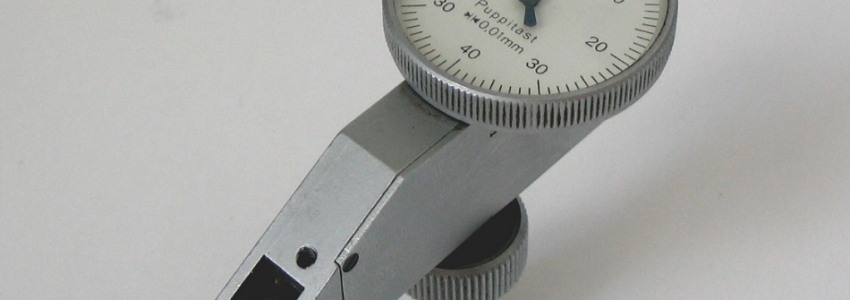
There are a number of different methods of employing a dial gauge for comparative purposes. Most readers will, of course, be familiar with this type of gauge, in which a plunger operates a pointer moving around a dial graduated in thousandths of an inch. The gauge is provided with a clamp, allowing it to be attached to the arm of a scribing block or similar carrier, so that the plunger of the gauge can be brought into contact with the component to be tested. In the case of a rotating part any eccentricity or lack of truth will immediately be revealed by fluctuation of the pointer.
More than one gauge can be employed at a time, enabling simultaneous checks to be made. At one car-manufacturing works, for instance, fifteen dial gauges are arranged to touch every vital part of an experimental back-axle assembly while the drive is being transmitted at maximum torque. The dial indicators reveal the side-thrust on the bevel pinion, the lift on the end of the pinion and on the crown wheel, the side-thrust of the crown wheel, and the end-float on the pinion. Side and endwise movement of the differential-bearing caps, movement of the differential cage, and any movement of the crown wheel on the opposite side can also be detected. Twist of the banjo axle-casing or deflection at the end of the casing, and also movement at the wheel hub, will be shown up.
A small dial gauge is frequently employed to check the circularity of bores or chamfered seatings which must be concentric with a pilot bush or guide, a typical instance being the valve-seatings of an internal-combustion engine. In this case a pilot rod of the correct diameter is inserted in the valve-guide or the pilot bush, and the dial gauge is fitted to the pilot, with the contact arm adjusted against the valve-seating or the interior surface of the bush, as the case may be. On setting the needle to zero and rotating the indicator slowly, movement of the needle will reveal inaccurate machining or grinding.
The cylinder gauge is a form of dial gauge which enables internal diameters to be accurately measured, both for circularity and parallelism of the bore. Modern instruments of this class are generally provided with self-centring slides enabling readings to be taken with the minimum of trouble. The dial gauge is in this case fitted with an adjustment enabling slight initial outward pressure of the plunger to be exerted against the cylinder wall before the needle is set to zero.
It is then a simple matter to rotate the gauge around the bore, movement of the needle revealing any ovality, and to slide it up and down to detect a tapering bore. With some types of cylinder gauge a cross-check can be applied by locking the contacts while the gauge is in the bore, and then measuring the actual diameter across the slide and the plunger of the gauge with a micrometer caliper.
The cylinder gauge can, of course, be employed during the final stages of machining or grinding a bore to size. A micrometer caliper should be adjusted to the exact size to which it is intended to grind the finished bore. The cylinder gauge should be fitted between the contacts of the micrometer and the dial of the gauge rotated to indicate zero. By passing the cylinder gauge into the bore at intervals during grinding, the exact amount of metal which it is necessary to remove will be indicated by the position of the needle on the minus side of the zero mark.
A different method of measuring internal diameters is with a micrometer caliper used in conjunction with a telescoping gauge. A telescoping gauge is first centred on the cylinder bush, or similar component, and the contacts are locked by tightening the handle. The gauge is then placed between the contacts of the micrometer caliper.
Apart from checking tolerances during production, a variety of actual measuring instruments are required, in the average factory or workshop. Ordinary calipers, although convenient for measurement and comparative purposes, are seldom used in production work, since the spring of the legs is bound to be a source of error, while the necessity for tapping the conventional type in order to adjust them is sufficient to condemn them for modern precision work. Vernier caliper gauges are, of course, invaluable when accurate measurements must be taken. In most cases, however, a micrometer caliper gauge or an inside micrometer gauge with a selection of distance-pieces is more generally used. In view of the wide use of the micrometer, which is to be found in various forms in nearly every workshop, a detailed description of its principle and use is hardly necessary.
It is, of course, imperative that the various gauges and measuring instruments just described should be capable of being checked from time to time, since with conventional gauges contact with the work is bound to cause wear and to impair their accuracy. The standard of accuracy in most large factories is the Johannson gauge block system.
These blocks are of varied dimensions, and are capable of being assembled together to verify any required dimension to an accuracy of l/100,000th of an inch. Such is the accuracy of the gauge blocks that if wrung together to exclude all air from between the surfaces in contact, they adhere with such tenacity that considerable force is necessary to pull them apart.
The blocks, when assembled in a special frame, can be used as snap gauges, length gauges, inside and outside calipers, and so on. The high degree of accuracy of the gauge blocks is maintained by keeping them at a constant temperature of .69 degrees Fahr. in the gauge room.
Do you have used machinery for sale?
Over 8,000 sellers have listed their surplus equipment with us since 2006.
Selling with Kitmondo is free, efficient and fast.
Start selling now