


-
Machinery
Choose from 20,028 used machinery listings
This article was originally published in Practical Engineering 1940 Vol1 No1. Information within this article is therefore correct as of 1940. The publication of this material aims to provide historical insight on the subject and its place in industry.
In many modern tool-rooms associated with the production of motor-car parts, where a high standard of precision is absolutely necessary, a great amount of overlapping or re-checking occurs. To the unenlightened, also those who have not given the matter sufficient thought, it appears to be time wasted, but to the management and inspection-department who have the results and experience of years laid before them, it proves to be economical. The human brain is always liable to error; those little "tricks" of omission, that make such a big difference, are the factors that must be continually held in check.
One result of this is the invention and improvement of modern scientific measuring instruments, such as the precision square, the micrometer, the Vernier slide gauge, the Vernier height gauge, the protractor and the sine bar. There are many very efficient protractors on the market at present, in nearly every case of American manufacture. Some are just graduated in degrees (°), whilst others, more costly, are divided up into minutes (1), but no matter how expensive and well-finished they may be, there is unfortunately always a chance of minute errors, an accumulation of which make a large error, and this in an angle that can so easily occur, increasing by the distance from the axis point, so that it becomes the usual practice in good-class tool-rooms to use a protractor in the primary stages of a job, and the sine bar combined with slip gauges as a final check.
Standard sine bars are made in two lengths—l0in. and 5in.—the equivalent measurement to build it up to the angle required is found by multiplying the sine given in engineering text-books by the length of the sine bar being used.
For instance, if one required to set a 5in. sine bar at 5° the figure given in the text-book is .08715in„ which represents a lin. radius; the amount then required for a 5in. bar will be .43575in., which is .08715in. multiplied by 5, and for a l0in. sine bar exactly double the amount will be needed.

In Fig. 1 will be seen an ordinary instrument as made by most of the leading precision tool manufacturers. They are rather expensive, because the process of manufacture is lengthy and necessarily costly. In the majority of cases they are made from high-grade cast steel, roughly machined, afterwards being hardened and tempered, and then rough ground. Owing to the fact that all forms of heat treatment, machining, and especially grinding, set up stress and agitation in the metal, the component parts are hung out in the open air for a period of from three to six months to enable the steel to regain its normal composure. They are then finally ground and lapped, and if supplied by eminent manufacturers, can be guaranteed to be within an error of .0001 in.
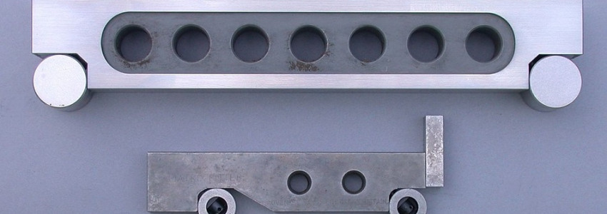
Straying from the standard, the design can be considerably improved, and in many modern tool-rooms this has been accomplished by experience of the requirements. The best design that has come under the writer's notice up to the present is shown in Fig. 2.

A is the bar, with a series of holes F, which are merely for lightening purposes. B are the rollers with a ground hole through the centre C, which will accept a standard mandrel. These rollers are retained in position by a stud D, and nut E drilled to accept a tommy-bar for assembly purposes. The three plates G are to stop the job from sliding off when the bar is set to an angle, and are detachable by removing the screws. This is one of the improvements to this sine bar, and the others are the roller retaining screws do not go right through as in most models, which are apt to be unsightly and inconvenient; the hole breaking the surface of the roller. Both sides of the bar are flush with the rollers, which in some cases protrude, making it awkward.
The ground hole through both rollers is a great advantage, as when a mandrel (a slide fit) is in position in each, the bar can be set with the Vernier height gauge, the former being packed up with steel strips or small jacks if slip gauges are not available.
It often occurs that a job which has to be checked or marked off to an angle is too heavy or dangerous to mount on a sine bar, or probably for the same reason cannot be built up to the angle on a surface plate, and in this case it is usual to first clamp the job on to an adjustable angle plate (made for this special purpose). These angle plates are often fitted with a ring graduated in degrees, which can be adjusted roughly to the required angle before the final adjustment with the sine bar in position. In very particular cases a sine bar must be built up to the required angle with slip gauges.
A slip gauge is a rectangular piece of hardened steel, the thickness of which is denoted on one of its faces, which can be purchased in sets fitted into cases. The measurements are so arranged that parts can be built up with extreme accuracy equalling almost any dimension to within 0.0001in. The first commercial gauges were marketed by a firm of precision tool makers—Messrs. Johansson, who are controlled by the Ford Motor Co., Ltd., of America. The process by which they are lapped to such a degree of accuracy and parallelism was, and now is, as far as this firm is concerned, a secret, but at the present time slip gauges are made by several firms all with their own specialised secret process of manufacture. The composition of sets is in most cases very similar, and one standard set contains 81 pieces, all of different sizes. In the first section are nine slips, the first one being 0.1001in., and the ninth, 0.1009in. In the next section there are 49 slips, beginning with 0.101in. and ending with 0.149in., then follows another line of 19 slips ranging from 0.050 to 0.950in. Then there are the four large gauges of l.000in., 2.000in., 3.000in., 4.000in. It will be gathered from this explanation that any pack can be built within 0.0001in. up to the capacity of the set, augmented by the larger size slips, should it become necessary.
The slip gauges produced by the firm already mentioned are in several grades. The best quality, which are used by many eminent firms as absolutely standard, are guaranteed to within limits of error averaging 2 to 5 parts in a million.
Slip gauges are in universal use in the majority of tool-rooms at present, not only for setting up a sine bar, but other practices where very fine measurements are necessary—for instance, if a pin projected from a jig or fixture that had to be 2.5005in. from the base, the usual method of checking this dimension would be on the surface plate with the use of the dial indicator set to the necessary amount of slip gauges and adjusted to zero, and then the point of the indicator passed over the projecting pin in question (Fig. 4).

Very similar to this is the practice of setting up a comparator, a method by which a group of articles is measured with extreme delicacy. This is an instrument with a permanent dial gauge which is adjusted to the required dimension with the aid of slip gauges, usually back to zero. The article requiring to be measured is then passed under the indicator as a comparison to the gauges to which the instrument was previously set. It will be seen from this that a group of articles can be infallibly checked with great rapidity.
Image Credit: Glenn McKechnie
Do you have used machinery for sale?
Over 8,000 sellers have listed their surplus equipment with us since 2006.
Selling with Kitmondo is free, efficient and fast.
Start selling now