


-
Machinery
Choose from 20,028 used machinery listings
This article first appeared in Practical Engineering 1940 Vol1 No25. The published information contained within the article is accurate as of 1940. This article describes techniques used in Engineering at the time.
The micrometer, or micrometer gauge, provides the most convenient method of taking accurate measurements of diameters and thicknesses of small parts, suitable for reading in thousandths of an inch; it is possible, however, to obtain instruments to read in- half-thousandths, or even ten-thousandths.
Before a micrometer can be used intelligently it is necessary to understand the principles upon which it is designed. It is perfectly straightforward, although to make use of it it is necessary to employ a little simple arithmetic. The essential of a micrometer is an accurately-threaded rod which can be turned in an equally accurate-threaded guide. The usual pitch of the thread for instruments made for English measure is 1/40in.; thus there are 40 threads per inch. In addition, there are instruments made for measuring in the metric system, and these have a screw with 20 threads per cm.—a pitch of half a mm.
It will be sufficient to consider the action of the micrometer calibrated in English measure, for the principle is precisely the same for any other calibration. The underlying idea is one in which a screwed spindle of 1/40in-pitch is passed through a threaded sleeve. Each time the screwed spindle is given a complete turn it will move backward or forward (according to the direction of turning) 1/40in.Thus, if a line were scribed along the thread and another were made along the outside of the sleeve, it would be a simple matter to count the number of turns given to the rod. This would be an indication of the number of one-fortieths of an inch that the spindle had been moved. If the screwed spindle were incorporated in a simple framework it would be possible to measure, although not very accurately, the diameter or thickness of any objects fitted between the two jaws of the gauge.
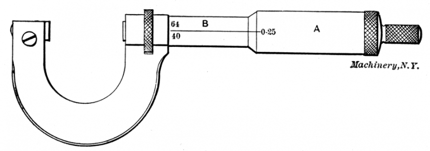
This is the basis of the micrometer gauge which shows a section through a micrometer of the simpler and widely-used type. It will be seen that there is an anvil with a square face arranged to meet the squared end of the spindle. On the spindle is fitted a thimble, a scale being formed round its end. A longitudinal scale is also provided on the sleeve. The only additional device is the locking ring. This consists of a knurled ring located in a slot in the frame. Inside this is a split ring with an inclined recess on its outer face; a small roller fits in this, so that when the knurled ring is turned the roller closes the split ring and so locks the spindle. The purpose of this locking device is simply to prevent movement of the spindle when a number of articles of similar size have to be checked.
The scale on the sleeve is divided into fortieths of an inch, and every fourth division is numbered from 1 to 10. On a 2in. micrometer there would be double this number of divisions. It will be seen from this that each number represents 1/10in., and each of the smaller divisions 1/40in. Round the bevelled end of the thimble there are 25 equal divisions, this time divided into fives and numbered 0, 5, 10, etc.
Now it is possible to see how the micrometer is read. When the spindle and anvil are closely together the end of the thimble is exactly on the zero line of the sleeve scale, and the zero mark on the thimble scale is exactly in line with the datum line forming the upper edge of the sleeve scale. If the thimble is given a complete turn its zero mark will again be in line with the datum mark on the sleeve and the edge of the thimble scale will be in line with the first division line on the horizontal scale. The reading would then be 1/40in.
If the thimble were given four complete turns the readings would be zero on the thimble scale and 1 on the sleeve scale. The reading would therefore be 4/40, or 1/10in. From this it will be seen how readings are taken in complete fortieths. If the reading on the horizontal scale were, for example, 3 (3/10in.), and the thimble were turned from the zero mark to the first small division, the gap would be opened by an amount represented by 1/25 of one complete turn of the thimble, which is 1/25 of 1/40; this is, of course, l/1,000in.
Assume that the sleeve has been turned one small division past the 3 mark, and then to the fourth line on the thimble or vernier scale. The reading is therefore : 3/10in., plus 1/40in., plus 4/1,000in. It is best to consider these dimensions as decimals instead of fractions, for their addition is then considerably simplified. There is a list of decimal equivalents engraved round the frame of most micrometers, and a corresponding list of equivalents is given in an accompanying table. Readers will be aware, however, that '1/10in, is the same as lin., that 1/40in. is the same as .025in., and that 1/1,000in. is equal to .001in.
If we now revert to the reading given above we can replace our sum of fractions by the following: .3in, plus .025in., plus .004in., which equals .329in. That is the distance between the anvil and the spindle of the gauge, and would be the thickness or diameter of a piece of metal which was a close fit in the gap.
Since the micrometer gauge is capable of giving readings which are accurate to 1/1,000m., it is evident that it must be properly used; any error could easily result in an incorrect reading. One of the most important points is that the gauge must be kept scrupulously clean and free from rust. This applies especially to the contacting faces. To ensure accuracy, the reading should occasionally be checked after closing the gap; when this is done the reading should be zero precisely.
The correct method of holding the gauge is with the frame resting in the palm of the right hand, while the thumb and finger hold the knurled portion of the thimble. By holding the instrument in this way the left hand is free to hold the material being measured or tested. Another item which should receive attention while setting the gauge to measure a diameter or thickness is that the thimble should be turned so that the material under test is made a close, but not tight, fit. It should just be possible, for example, to move a rod through the gap by applying slight pressure. Before taking a measurement see that the metal is clean and free from grease or oil.
To simplify the setting, many of the better-class micrometers are fitted with a ratchet device at the end of the thimble. This operates on the principle of a slipping clutch. Thus, when the spindle encounters resistance to further movement a pawl slips out of engagement with the ratchet teeth. Once the "feel" of the gauge has been obtained from a certain amount of experience, the instrument can be used easily and with confidence. But practice is necessary, despite the apparent simplicity of construction.
It is to be expected that with a sensitive gauge of this kind slight wear may throw out the readings. Wear is most likely to occur on the spindle thread, and to compensate for this a collet device is provided at the end of the barrel. The end is split and is taper-threaded to receive a circular nut. This is drilled to receive the point of a C-spanner. After wear has taken place, therefore, the procedure is to screw back the thimble until the nut is revealed, and then to apply the C-spanner which is generally supplied with the gauge.
It is possible that, after extended use, or if the gauge should have been accidentally dropped, the accuracy of reading may be impaired due to movement of the anvil. Therefore, on most high-grade instruments an adjustment is provided by means of which the anvil can be moved so that the gap is just closed when the reading is zero. In some cases the anvil must be lightly tapped after removing a set screw; in others the anvil can be turned on a thread by using a spanner provided; in other cases the outside end of the anvil has a screwdriver cut, and the threaded anvil may be turned after slackening a locking nut.
The usual sizes of micrometer are lin. and 2in., this representing the largest opening. For most purposes the smaller size is suitable, but the latter may be required for larger work. There are some variations in the shape of the frame. Sometimes the frame is made deeper so that sheet metal can be more easily dealt with. Other models have a cut-away frame, the frame being narrowed at the anvil end so that it can be used in places where the ordinary frame may be too big. A modification of the normal type of micrometer is one made for measuring threaded rods.
In some examples it will be seen that there is a V-cut in the anvil and that the end of the spindle is turned down to a point. In other cases both anvil and spindle are pointed. Another special type of micrometer, useful for measuring spheres and other small, accurate parts, has as its chief feature the provision of a V-block anvil which serves to locate the work accurately.
Besides the outside micrometer which has been considered so far, there are inside-measuring types. In this type the frame is omitted, and there is simply a barrel, thimble and short spindle. Additionally, however, there is a set of interchangeable spindles in 1/2in. ranges. The movement of the screw is limited to 1in., but any diameter can be measured simply by using the appropriate spindle.
Do you have used machinery for sale?
Over 8,000 sellers have listed their surplus equipment with us since 2006.
Selling with Kitmondo is free, efficient and fast.
Start selling now